Yes, cable length can affect USB-C charging, but length is only one part of the circuit. A longer cable normally has more conductor resistance than an otherwise identical shorter cable. At higher current, that resistance creates more voltage drop and heat inside the cable. Whether a phone, tablet or laptop actually charges more slowly also depends on conductor size, connector quality, the cable’s declared current capability, the charger, the device and the power profile they negotiate.
The short answer: compare like with like
If two cables use the same conductor material, cross-section, connector construction and assembly quality, the longer cable will usually have greater loop resistance. That does not mean every short cable is good or every long cable is slow. A well-designed longer cable can outperform a poorly built short one. The useful question is not “What is the longest USB-C cable?” but “Can this exact cable deliver the required function at this length with acceptable loss?”
Start by defining the target device and charger. A cable used for a low-current accessory has a different job from one expected to charge a laptop. Then verify power, data and video requirements separately. A cable’s charging capability does not automatically prove its data rate or display support.
Why a longer cable creates more opportunity for voltage drop
Electrical resistance rises with conductor length and falls as conductor cross-section increases. In a charging cable, current travels to the device and returns, so the relevant path includes both sides of the power circuit plus the contacts and terminations. The simple relationship is useful: voltage drop equals current multiplied by resistance. Doubling current doubles the drop across the same resistance; losses inside the cable rise even faster because resistive heating is related to the square of current.
This is why a cable that appears fine at light load may behave differently when the device asks for more current. It is also why an unloaded voltage reading is not enough. With almost no current flowing, even a cable with excessive resistance may show a normal-looking voltage.
| Variable | Why it matters | What to verify |
|---|---|---|
| Length | More conductor length generally adds resistance. | Finished-cable resistance or loaded voltage at the intended length. |
| Conductor cross-section | Larger power conductors can reduce resistance, all else equal. | Supplier construction record plus finished-cable measurement. |
| Current | More current produces more drop across the same resistance. | The actual negotiated profile and sustained load, not charger wattage alone. |
| Connectors and joints | Contact and termination resistance add to conductor loss. | Connector temperature, mechanical fit and sample-to-sample consistency. |
| Cable identity | Some higher-current USB-C cables must electronically declare capability. | Correct identity and marking for the intended current; do not infer data support. |
Charging negotiation and cable loss are different checks
USB Power Delivery lets a compatible source and sink agree on a power contract. The USB-IF USB Power Delivery overview describes power delivery as a system involving the source, cable and device. A successful negotiation does not erase cable resistance. The charger can offer a profile, the device can request it and the cable can identify a capability, while excessive loss or a weak connector still reduces the electrical margin at the device.
Likewise, a lower observed charging rate does not prove that length is the cause. The device may limit power because of battery state, temperature, software policy or charger capability. Before blaming the cable, compare the same charger and device under the same conditions and change only the cable.
Do not turn a compliance limit into a universal length rule
The current USB Type-C Functional Test Specification includes electrical checks and defined test conditions for cable assemblies. Those requirements are useful evidence boundaries, but they do not create one universal “safe length” for every power level, conductor design and device. The applicable cable category, current rating, test setup and specification revision matter.
A supplier should therefore avoid approving a cable from a nominal gauge claim alone. Finished assemblies include connector contacts, solder or weld joints, strain relief and manufacturing variation. Measure the complete cable, not just a piece of raw conductor.
Connector condition also changes over the product life. Contamination, a loose receptacle or repeated side load can add intermittent contact resistance even when the cable conductors are adequate. A cable approval should therefore include mechanical fit and repeatable insertion checks, while a field diagnosis should inspect the charger and device receptacles as well. Replacing the cable cannot repair a worn device port, and a new long cable should not be approved from one clean bench connection alone.
Choose length by use case, not convenience alone
| Use case | Selection priority | Evidence to request |
|---|---|---|
| Phone near a wall charger | Use only the reach needed; reduce clutter and repeated bending. | Declared current capability, connector durability and loaded check with target phones. |
| Tablet on a desk or counter | Balance reach with a stable high-current path. | Finished-cable resistance and sustained test at the intended profile. |
| Laptop charging | Power identity, conductor loss and connector temperature have less margin for guesswork. | Exact supported power range, cable identity record and device-side validation. |
| Vehicle or routed installation | Routing, strain relief and ambient conditions matter alongside length. | Installed routing sample, bend/strain review and repeatable load test. |
| Charging plus high-speed data or video | Power and signal performance must both pass. | Separate power, data-rate and display evidence for the finished length. |
A controlled cable validation sequence
- Freeze the system. Record the exact charger, device, battery state range, firmware and ambient conditions.
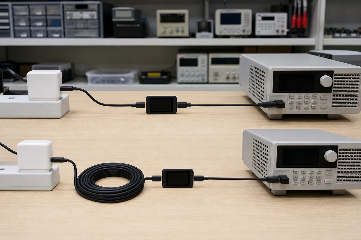
- Choose a known short reference. Confirm the system can reach the expected charging behavior before evaluating the longer candidate.
- Record the negotiated profile. Use an appropriate USB-C/PD analyzer without relying on a charger label or marketing wattage.
- Measure under sustained load. Observe voltage and current at consistent points after the system settles. An open-circuit reading is not a substitute.
- Check the whole assembly. Inspect both connectors, strain relief and cable surface for abnormal temperature, intermittent behavior or mechanical looseness.
- Repeat across samples. One good cable does not prove production consistency. Compare multiple units and retain the approved reference.
- Repeat the real function. If the requirement includes data or video, validate those functions separately at the finished length.
Common selection mistakes
- Buying by wattage printed on the package. The source, cable and device must all support the intended profile.
- Assuming an e-marker fixes voltage drop. Cable identity can communicate capability; it does not reduce physical resistance.
- Using conductor gauge as the only acceptance criterion. Finished-cable contacts and terminations also contribute.
- Comparing cables under different battery conditions. A device near full charge may request less power and hide the difference.
- Extending a test result to every device. Charging policy and connector behavior can vary by device and firmware.
What to put in a cable requirement
Define connector types, finished length and tolerance, target source and devices, required charging profiles, current capability, data or display requirements, jacket and bend needs, and the acceptance method. If an existing setup is already underperforming, use the USB-C slow-charging diagnostic guide first so a charger or device limit is not misclassified as a length problem.
When those requirements are clear, review the available USB-C to USB-C charging cable category and ask for evidence tied to the exact length and construction you plan to approve. The correct length is the shortest practical cable that still meets the real routing need and passes the defined system test.