USB cable shielding uses conductive layers and controlled termination paths to limit electromagnetic energy entering or leaving the cable assembly. It supports signal integrity and electromagnetic compatibility, especially as data rates and installation complexity increase. Shielding does not make every cable high speed, increase charging wattage, or prove that the finished assembly is certified.
The complete path matters: signal pairs, foil or braid, drain or bonding path, connector shell, host, device and physical routing all interact. A cable can contain metallic material and still perform poorly if the shield is interrupted, badly terminated or unsuitable for the required USB mode.
Internal shield and outer braid have different jobs
A buyer may see “braided USB cable” and assume the braid is electrical shielding. In most product descriptions, however, that phrase refers to a nylon or textile sleeve outside the cable jacket. It may change abrasion resistance, flexibility and appearance, but it does not by itself describe the cable’s conductive shield.
The braided USB-C cable guide covers those mechanical questions. Electrical shielding is normally placed beneath the outer jacket and may use foil, woven metal braid, shielded subassemblies or a combination selected for the cable design.
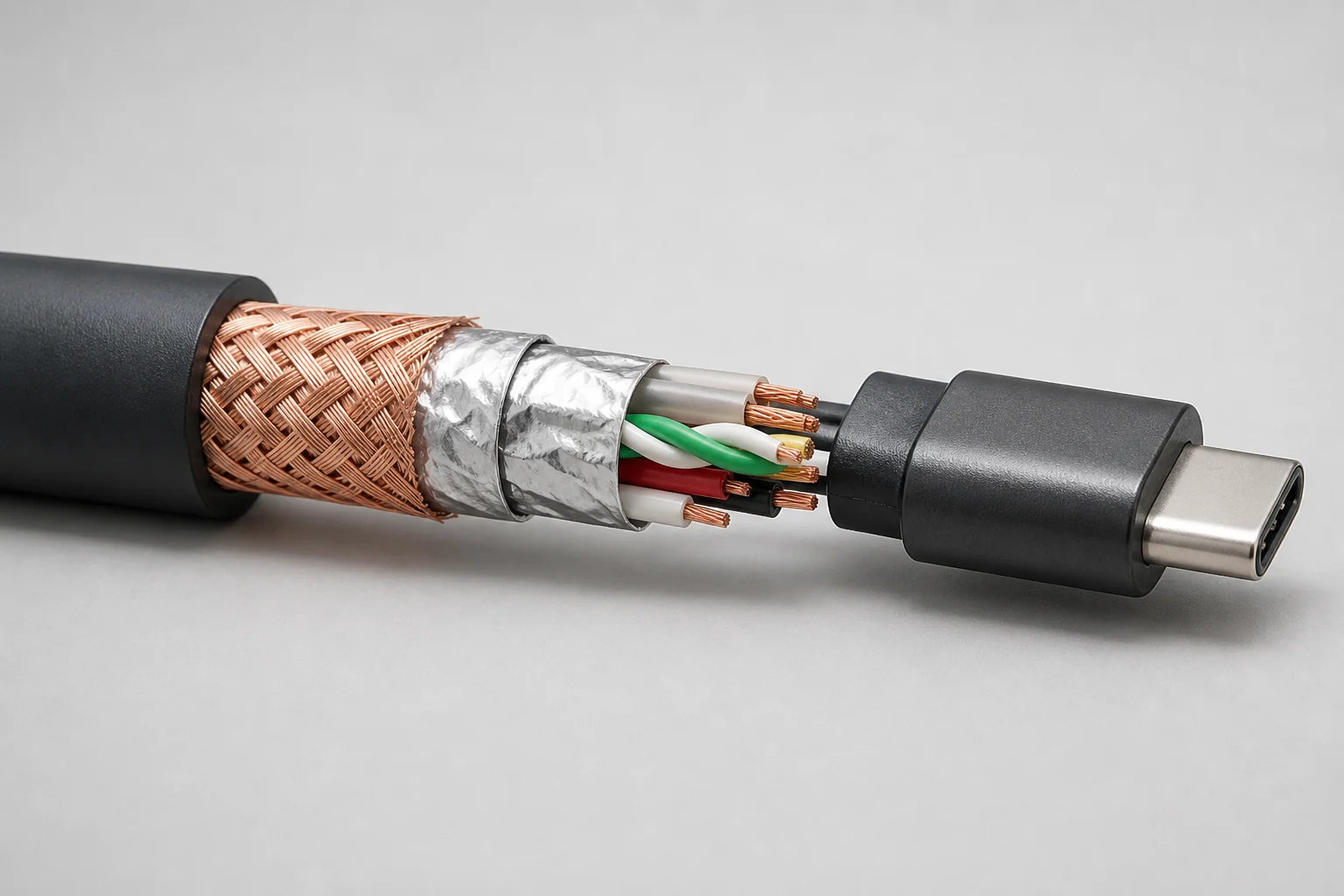
What each part contributes
Signal pairs and power conductors
USB data travels on defined conductor pairs, while separate conductors carry power and return current. Pair geometry, impedance, conductor construction and length influence electrical performance. Shielding surrounds or partitions these elements; it does not replace correct conductor design.
Foil shield
A conductive foil can provide broad, continuous coverage with limited added thickness. It must remain continuous through the intended path and be terminated as the assembly design requires. A loose piece of foil visible in a cut sample is not proof of finished-cable performance.
Metal braid
A woven copper or tinned-copper braid can provide a robust conductive layer and a practical connection to the connector shell. Coverage, wire material, flexibility and termination affect the result. The electrical braid sits under the jacket; it should not be confused with an exterior fabric sleeve.
Drain or bonding path
Some constructions use a drain wire or another bonding method to create a repeatable connection along the shield. The relevant question is whether the shield system is continuous through the finished connector assembly, not whether one internal component appears in a marketing image.
Connector shell and device interface
The connector shell, receptacle and product enclosure complete part of the electromagnetic path. A well-constructed cable cannot correct a host or device with an incompatible interface, poor grounding strategy or unsupported USB mode.
Shielding helps manage two directions of interference
Emissions are unwanted electromagnetic energy leaving the cable and affecting nearby systems. Immunity describes the ability of the connection to keep working when external electromagnetic energy is present. The same conductive structure can contribute to both, but the test setup, frequency range and acceptance limit are not interchangeable.
The USB-IF USB Type-C compliance document includes cable shielding-effectiveness requirements for defined assembly categories. That shows shielding is a measurable part of compliance, not a decorative claim. The cited document is a program reference; the current applicable specification and test plan should be confirmed for the exact cable category.
What shielding cannot prove
- Data rate: a shielded cable may still be wired or qualified only for a lower USB data mode.
- Charging power: shield material does not identify the conductor current rating, e-marker state or USB PD contract.
- Video support: a USB-C connector and shield do not prove DisplayPort Alt Mode, USB4 or Thunderbolt capability.
- Certification: a cutaway image or “double-shielded” label is not a searchable certification record for the finished product.
- System immunity: routing beside motors, converters or radio equipment can still create a difficult environment.
- Mechanical life: shielding does not replace a suitable jacket, strain relief and bend design.
A six-question buyer matrix
| Buyer question | Useful evidence | Weak shortcut |
|---|---|---|
| Which USB function must work? | Connector pair, data mode, power class, video need and cable length | “USB-C cable” as the entire specification |
| What is being shielded? | Assembly drawing or construction description tied to the exact model | A generic cutaway reused across several products |
| How is the shield terminated? | Finished-assembly description and connector-shell continuity method | Counting foil and braid layers without the termination path |
| Which requirement applies? | Current USB-IF specification or other named requirement for the cable type | An undefined “EMI protected” badge |
| How was it checked? | Named test method, setup, sample identity, limit and result | A meter photo without method or acceptance limit |
| Will it work in the system? | Host-cable-device test in the intended routing and noise environment | A bench result with a different host, length or installation |
Match construction to the application
Charging-only deployments
Power conductors, connector quality and supported charging behavior remain the first checks. Do not add a high-speed shielding claim to a cable that is not intended or verified for high-speed data.
High-speed storage, hubs and displays
Define the exact data or video mode, cable length, connector orientation and complete host-device path. Higher-speed links leave less room for uncontrolled construction or routing changes.
Audio, cameras and measurement devices
Intermittent noise or disconnects may involve the cable, connector, host power, device design, grounding or nearby equipment. Use a known-good cable and controlled routing to isolate the variable before changing the specification.
Kiosks and fixed installations
Record nearby power supplies, motors, radio transmitters and cable bundles. Shielding should be evaluated as part of the installation, together with bend radius, strain relief and connector retention.
Read the marking, then verify the assembly
The USB-IF cables and connectors guidance separates power and data markings for USB-C-to-USB-C cables in its compliance program. That is a useful reminder that connector shape, power, data and shielding are different dimensions. If a supplier claims USB-IF certification, verify the exact finished product rather than transferring evidence from a similar cable.
Frequently asked questions
Is a braided USB cable shielded?
Not necessarily. An exterior textile braid is usually a mechanical jacket feature. Electrical shielding uses conductive material beneath the jacket and depends on its termination through the finished assembly.
Does more shielding always make a better USB cable?
No. The construction must match the USB mode, length, flexibility and connector design. Extra layers that are poorly terminated or mechanically unsuitable do not guarantee better system performance.
Can shielding fix a slow-charging cable?
Shielding is not the primary proof of charging capability. Check conductor and connector resistance, cable current and power rating, the charger-device protocol and the complete negotiated path.
Specify function before layers
Start with the connector pair, required data rate, charging power, video function, length and installation environment. Then define the shield construction, termination and evidence needed for that use. The cables category provides a broad product route, but the exact electrical construction and qualification should be confirmed for the proposed cable before final selection.